- All
- Product Name
- Product Keyword
- Product Model
- Product Summary
- Product Description
- Multi Field Search

Views: 147 Author: Site Editor Publish Time: 2026-05-23 Origin: Site


Handling aggressive industrial fluids is a complex engineering challenge. You must balance extreme corrosion resistance, high-pressure containment, and multi-directional movement absorption simultaneously. Traditional pure metal joints often fail under chemical attack because they rely on extremely thin walls ranging from 0.15mm to 2mm. Conversely, standard rubber joints usually lack the pressure ratings and extreme temperature tolerance required for high-risk applications. This forces engineers into a difficult compromise between flexibility and durability.
Fortunately, engineered chemical resistant expansion joint solutions solve this dilemma. Specifically, hybrid rubber-metal designs combined with specialized inner liners offer an optimal, compact alternative. They outperform space-consuming piping expansion loops while maintaining structural safety under severe fluid conditions. In this guide, we will explore why hybrid designs excel in harsh environments. You will learn how to specify materials correctly and master the STAMPED framework. We will also cover structural nuances and common installation errors to help you ensure long-term pipeline reliability.
Material Matching is Critical: Elastomer and liner selection must align strictly with the chemical medium (e.g., PTFE liners for universal resistance, FPM/Viton for high-temperature petrochemicals).
Hybrid Durability: Rubber metal expansion joints combine the vibration dampening of thick elastomers with the pressure-retaining strength of metal reinforcements.
Fail-Safe Reliability: Advanced industrial pipe connectors utilize multi-ply or redundant outer metal bellows to prevent catastrophic leaks during up-set temperature conditions.
Precision Specification: Utilizing the STAMPED criteria prevents the most common procurement and operational failures.
Relying on a single material often leads to premature pipeline failure in harsh chemical applications. Hybrid designs deconstruct the product anatomy to leverage the best properties of multiple materials. A well-engineered rubber metal expansion joint outperforms rigid, all-metal setups by introducing unparalleled flexibility and acoustic control.
Standard metal bellows feature walls measuring just 0.15mm to 2mm thick. These thin walls transmit noise and remain highly susceptible to chemical pitting. In contrast, thick rubber walls measure between 12mm and 25mm. This substantial mass inherently dampens acoustic impedance. It absorbs severe mechanical vibrations, including destructive pump cavitation and unexpected water hammer forces. The elastomer matrix dissipates energy far more effectively than steel.
Installing a non-metallic or internally lined chemical pipe joint also eliminates galvanic corrosion. Diverse metal pipes joined directly will create an electrochemical circuit. This circuit accelerates localized rusting. Interposing a hybrid joint breaks this direct metal-to-metal contact, completely neutralizing galvanic risks.
Understanding the structural integrity requires looking at the anatomy of these connectors. They typically feature three primary engineered layers:
Leak-Proof Inner Tube / Liner: This acts as the first line of defense. It isolates the aggressive fluid from the structural components. Engineers often specify a 1-3mm PTFE lining for maximum chemical inertness.
Fabric & Metal Reinforcement: The carcass handles pressure spikes. Manufacturers embed high-tensile internal metal wire rings alongside synthetic fabrics, such as Kevlar®, to maintain structural shape under high pressure.
Outer Cover: The robust elastomer exterior protects internal layers from environmental hazards. It shields the reinforcement from weathering, UV degradation, and external chemical drips.
Specifying a corrosion resistant connector requires an exact match between the fluid medium and the internal liner. Choosing the wrong elastomer is the most frequent cause of rapid degradation.
PTFE (Teflon) stands as the gold standard for universally aggressive and reactive chemicals. It possesses highly hydrophobic properties and an extremely low friction coefficient. This ensures smooth fluid passage while resisting nearly all industrial acids and bases.
For high-temperature petroleum products and strong acids, FPM (Viton) is necessary. FPM handles intense heat and aggressive hydrocarbons seamlessly. You must contrast this with NBR or HNBR. NBR strictly serves applications involving oils, fats, and natural gas. Engineers must strongly warn against using EPDM for any oil-based media, as petroleum rapidly degrades EPDM compounds.
EPDM excels in specific scenarios like hot water circulation, industrial cooling networks, and mild acids or alkalis. Alternatively, Hypalon (CSM) provides targeted resistance for specific concentrated chemical and gas applications. Finally, operations pumping abrasive chemical slurries or high-particulate suspensions require Natural Rubber (NR) blends. NR offers superior mechanical abrasion resistance compared to synthetic options.
Material / Liner | Primary Industrial Applications | Strictly Avoid Using For |
|---|---|---|
PTFE (Teflon) | Highly reactive chemicals, universal acids, high-purity fluids. | Applications requiring extreme physical stretching. |
FPM (Viton) | High-temperature petroleum, strong acids, solvents. | Low-temperature refrigeration systems. |
NBR / HNBR | Oils, fats, natural gas, petroleum products. | Strong acids, hot water, steam. |
EPDM | Hot water, cooling water, mild acids and alkalis. | Any oil, fat, or petroleum-based product. |
Natural Rubber (NR) | Abrasive chemical slurries, high-particulate suspensions. | High-temperature oils, strong chemical solvents. |
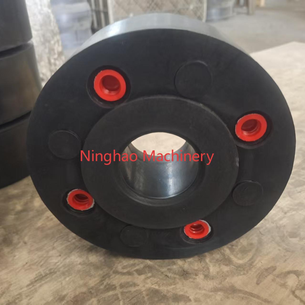
High-quality components separate themselves from commodity parts through subtle structural nuances. Evaluating an industrial expansion joint requires looking beyond basic dimensions to understand internal geometry and redundancy.
Optimized arch geometry plays a vital role. Lower and wider arch profiles provide maximum axial, lateral, and angular movement capabilities. They achieve this without increasing the face-to-face installation space. This design significantly reduces flange reaction forces, alleviating stress on adjoining pumps and valves.
Flange face engineering also impacts long-term success. True 90-degree molded flanges ensure smooth flow. Many inferior products utilize sweeping radii at the flange corner. Sweeping radii create dead zones between the adjoining pipe flanges. These gaps cause fluid turbulence, entrap abrasive particulates, and foster localized chemical concentration. A true 90-degree face eliminates these hazardous dead zones.
Chemical pipelines face the constant threat of extreme temperature spikes, known as up-set conditions. Advanced hybrid designs incorporate sophisticated fail-safe mechanisms to prevent catastrophic events. In some high-risk configurations, an inner PTFE or rubber liner handles the primary chemical containment. If this inner liner melts during a severe temperature spike exceeding 500°F, an outer multi-ply metal bellows takes over. This redundant metal layer maintains pressure integrity at temperatures up to 1200°F. It holds the hazardous fluid long enough for operators to safely shut down the system without an external spill.
Preparing accurate specifications dictates the success or failure of any pipeline connection. Engineers rely on the STAMPED framework to build an authoritative checklist before procurement. Missing a single variable often causes a chemical joint to fail.
S (Size & Face-to-Face): You must factor in existing pipeline dimensions carefully. Document the exact inner diameter and the allowable face-to-face installation gap.
T (Temperature): Account for continuous operating temperatures and map out potential intermittent spikes. The material must survive the absolute peak temperature, not just the average.
A (Application & Movement): Calculate the exact required compensation. Evaluate axial compression, axial elongation, lateral deflection, and angular rotation. Consider concurrent movements, as they reduce the overall allowance.
M (Medium): Identify the specific fluid. Document the concentration percentages and phase state (liquid, gas, or abrasive slurry). This dictates the inner liner material absolutely.
P (Pressure & Vacuum): State both maximum operating pressure and expected surge pressures. Crucially, specify vacuum conditions. Vacuum applications, especially in larger pipe diameters, require internal metal vacuum support rings or spirals. Without these rigid supports, the rubber walls will collapse inward.
E (Ends/Fittings): Define your flange standards (e.g., ASME, DIN). Confirm drilling patterns and request molded sealing beads. Integrated sealing beads ensure a low-torque, leak-free connection.
D (Delivery & Control Units): Determine if your system requires external hardware. Limit rods and control units prevent the joint from over-extending under high system pressure.
Even the most perfectly engineered product will fail if installed incorrectly. Operational experience highlights several consistent risks that maintenance teams must monitor.
Failure to remove shipping bars ranks as the number one installation error globally. Manufacturers attach rigid steel shipping bars across the flanges to hold the joint at its neutral length during transport. Mechanics sometimes leave these bars attached after bolting the flanges together. Leaving shipping bars installed locks the component rigidly in place. Once the pipeline thermally expands, the restrained system forces will tear the adjacent piping or destroy the joint completely. You must remove them prior to operation.
Improper anchoring and guiding causes another frequent failure mode. A critical piping layout theorem states that expansion joints do not absorb pressure thrust. The fluid pressure constantly tries to push the pipe apart. The system must feature engineered fixed points, known as main anchors, to hold the pipe securely. Furthermore, operators must install pipe guides to direct thermal movement purely along the intended axis. Without proper anchors and guides, the joint will wildly over-extend and rupture.
Particulate buildup poses a severe threat in chemical slurry applications. Chemical crystallization or solid matter often accumulates inside the open arch. Over time, this solid mass causes the rubber arch to lose flexibility and harden. When the pipe eventually moves, the stiffened arch cracks. To combat this, engineers propose using filled arches or integrating specialized particulate barriers. These solutions keep solids out of the flex zone while retaining necessary movement capabilities.
Evaluating a industrial pipe connector requires moving far beyond basic flange dimensions. Specifiers must critically assess exact fluid chemistry, system pressure thrusts, and potential fail-safe requirements. You cannot compromise on material selection when handling aggressive industrial media.
We strongly encourage engineers to utilize the complete STAMPED criteria. Gathering precise operational data before requesting engineering drawings guarantees a safer, more reliable pipeline. Taking shortcuts on temperature limits or vacuum ratings leads directly to catastrophic leaks.
Take action today by reviewing your current pipeline stress points. Consult with application engineers to analyze detailed fluid compatibility charts. By exploring custom hybrid solutions tailored to your facility, you ensure your next installation delivers maximum safety and longevity.
A: Yes, they can handle vacuum conditions safely. However, they require internal acid-resistant steel support rings or spirals. As pipe diameters increase, the rubber walls lose their natural resistance to inward collapse. Specifying these internal metal supports prevents the joint from imploding under negative pressure.
A: You should choose a PTFE-lined rubber joint when your system suffers from high mechanical vibration or structural noise. It is also necessary when you need to break galvanic currents between dissimilar metal pipes, all while maintaining extreme chemical resistance against aggressive fluids.
A: They are supplementary steel hardware assemblies attached across the flanges. They restrict the total movement of the joint. By physically blocking over-extension, they prevent the pipeline pressure thrust from ripping the bellows apart in systems lacking adequate main anchors.