- All
- Product Name
- Product Keyword
- Product Model
- Product Summary
- Product Description
- Multi Field Search

Views: 146 Author: Site Editor Publish Time: 2026-07-13 Origin: Site


High-pressure industrial pipeline systems constantly face two major operational threats. Mechanical stress from daily vibration and thermal expansion continuously wears critical components down. Meanwhile, sudden operational anomalies heavily destabilize the entire network. These dangerous anomalies include unexpected pressure drops or rapid flow changes. Relying solely on rigid piping leaves infrastructure highly vulnerable. Passive components alone cannot handle extreme dynamic shifts. This inadequate approach often leads to catastrophic blowouts or massive undetected leaks.
True system resilience demands a comprehensive, dual-layered approach. You must control mechanical movement physically using a tie rod rubber joint. You must also pair this physical restraint alongside active electronic monitoring. We achieve this intelligence via a reliable water flow alarm. This guide provides a deep technical evaluation framework for facility engineers. We will explore exactly how integrating these complementary systems protects your operations. You will learn to meet strict industrial compliance and modern safety standards effectively.
A tie rod rubber joint physically absorbs system vibration while preventing dangerous over-extension from pressure thrusts.
A water flow alarm provides immediate, active monitoring, triggering shutoffs before mechanical failures escalate into facility-wide flooding.
Combining mechanical restraint with active flow monitoring creates a defense-in-depth architecture essential for modern pipeline safety equipment compliance.
Proper specification requires matching the tie rod's pressure rating with the flow alarm's sensitivity to avoid false alerts and component fatigue.
Unmanaged pressure surges quietly destroy complex piping infrastructure over time. They directly lead to premature flange wear and severe pump damage. These destructive forces multiply across your facility layout. Ultimately, unmitigated mechanical failures cause extremely costly unplanned downtime. Production halts completely when a main line ruptures. Facility managers scramble to replace shattered components under immense stress. You cannot afford to leave your hydraulic systems exposed to these raw physical forces.
Standard expansion joints handle basic physical shock quite well. However, single solutions possess glaring limitations. A basic joint can easily over-extend under sudden pressure spikes. It acts as a weak link during a violent surge. Conversely, electronic sensors detect problems accurately and swiftly. Yet, a sensor cannot physically absorb a massive water hammer impact. Relying on just one defense mechanism creates a dangerous operational blind spot.
An effective safety architecture demands a hybrid, multi-layered approach. It must physically restrain excessive piping movement during operation. Simultaneously, it must alert operators to internal flow irregularities in real-time. This combination forms the ultimate success criteria for modern plant safety. You secure both the mechanical integrity and the operational awareness of your entire network.
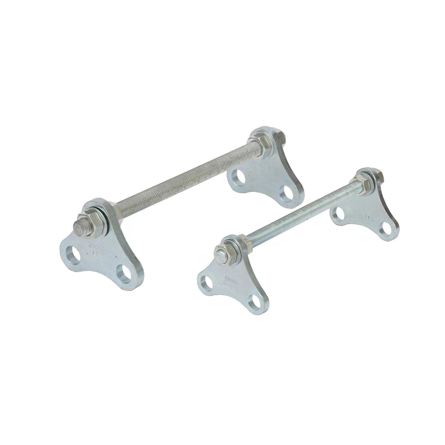
Control units act as crucial mechanical limiters within high-stress networks. Industry professionals frequently call them rubber joint tie rods. They permit necessary lateral and angular pipe movement freely. At the same time, they aggressively stop the joint from expanding past its designed maximum length. This hard limit prevents the flexible body from tearing apart under tension.
Internal fluid pressure always generates a powerful hydrostatic thrust force. Tie rods directly counteract this massive internal force. They absorb the extreme tension safely away from the delicate rubber bellows. This rigid physical barrier protects adjacent fragile equipment entirely. Pumps and sensitive valves survive because the rods carry the structural burden.
Thorough evaluation criteria ensure you select the correct mechanical restraints. Material selection matters immensely for long-term durability. You must perfectly match the internal elastomer to your transported media. Next, rigorously evaluate the gusset plate and rod strength. You must assess the tensile strength requirements based on your maximum system surge pressure. Finally, consider acoustic and vibration dampening capabilities. The flexible rubber body absorbs intense kinetic energy efficiently. This action dramatically extends the lifecycle of connecting pumps and valves.
Elastomer Material Type | Ideal Media Compatibility | Common Industrial Application |
|---|---|---|
EPDM | Water, dilute acids, alkalines | Cooling towers, HVAC systems, wastewater |
Nitrile (Buna-N) | Oils, hydrocarbons, petroleum | Refineries, fuel processing, chemical lines |
Neoprene | Moderate chemicals, abrasive slurries | Mining operations, heavy slurry transport |
PTFE Lined | Highly aggressive acids and solvents | Pharmaceutical processing, pure chemical handling |
Industry best practices strongly advise verifying the exact flange dimensions before installation. A slight mismatch in bolt holes completely negates the control unit's structural integrity. You must ensure your gusset plates distribute the load evenly across the entire flange face. This prevents localized stress fractures on your expensive piping components.
A sophisticated water flow alarm constantly measures internal kinetic energy or fluid velocity. It instantly detects dangerous anomalies deep inside the network. These sudden changes indicate major pipe ruptures, severe blockages, or catastrophic pump failures. The sensor acts as the primary nervous system for your fluid transport layout. It never sleeps or misses a rapid drop in line pressure.
Smart integration elevates a basic standalone sensor into a comprehensive water conservancy alarm network. You can seamlessly tie these modern alarms into broader facility control systems. SCADA and PLC systems automatically trigger emergency shut-off valves based on these instant alerts. This immediate digital communication alerts EHS personnel before minor leaks become massive disasters.
You must rigorously evaluate your electronic monitoring options before purchase. Pay close attention to these specific evaluation criteria:
Sensitivity vs. False Positives: You must carefully select the right actuation threshold. This specific calibration prevents alarms from triggering during normal, minor pressure fluctuations.
Fail-Safe Design: The alarm mechanism must function reliably at all times. It needs to perform perfectly during sudden power outages or extreme environmental conditions.
Material Housing: Ensure the external casing resists corrosion. NEMA 4X or IP67 ratings protect delicate electronics from heavy industrial washdowns.
Output Protocol: Verify the sensor outputs compatible signals. Common industrial standards include 4-20mA or Modbus RTU communication protocols.
A common mistake involves choosing a highly sensitive sensor for a naturally turbulent line. You will suffer constant false alarms. Operators quickly learn to ignore these frequent alerts. This dangerous habit completely undermines the purpose of the safety system.
These two essential components interact perfectly during a major system event. Consider a severe, unexpected water hammer incident. A valve closes too quickly, sending a massive shockwave down the pipe. The mechanical joint physically absorbs the initial kinetic shock immediately. This flexible response prevents an instant, catastrophic pipe burst. Simultaneously, the internal flow fluctuates wildly.
The electronic flow sensor instantly detects this resulting flow irregularity. It rapidly sends a digital signal to your central control panel. The system automatically triggers an emergency pump shutdown sequence. This coordinated response stops further fluid delivery into the stressed zone. The physical component bought you crucial seconds. The electronic component executed the permanent solution.
Pairing mechanical safeguards alongside active monitoring fulfills incredibly stringent requirements. It easily meets strict industrial insurance policies and tough environmental protection standards. High-quality pipeline safety equipment aggressively prevents massive, reportable chemical spills. Insurance auditors specifically look for this exact defense-in-depth architecture during site evaluations. They want to see redundancy built directly into the process.
Ultimately, this robust dual architecture heavily extends the mean time between failures (MTBF). Your maintenance teams spend less time fighting sudden fires. They spend more time optimizing overall plant efficiency. It thoroughly safeguards the entire network against terrifying cascading failures.
Installers face a major danger daily: over-tightening the control rods. If you tighten the nuts too much, you completely lock the rubber joint in place. This fatal mistake completely defeats its primary vibration-absorbing purpose. The joint basically becomes a rigid piece of pipe. You must precisely calculate and set the correct functional gap. Consult the exact manufacturer dimensional charts before applying any wrench.
You must also strictly avoid turbulent piping zones. Install all flow monitors at specific, calculated distances from elbows and pumps. Keep them safely away from the flexible joints themselves. Industry standards usually dictate installing sensors at least ten pipe diameters away from any disruption. This strategic placement ensures highly accurate, smooth laminar flow readings.
Let us debunk the dangerous "set it and forget it" myth immediately. True facility safety requires rigorous, continuous vigilance. You need routine visual inspections targeting early rubber degradation or cracking. You must also conduct periodic calibration tests for the electronic flow sensors.
Observe these critical installation and maintenance rules closely:
Never paint over the flexible rubber body. Paint solvents quickly degrade the internal elastomer compounds.
Always use a calibrated torque wrench when tightening flange bolts. Uneven pressure causes immediate gasket failure.
Schedule bi-annual flow switch tests. Manually simulate a low-flow event to ensure the PLC triggers the valve.
Inspect gusset plates for early signs of rust or mechanical bending every quarter.
Proper implementation bridges the gap between theoretical safety and actual operational resilience. Do not rush the installation process. A poorly installed safety device is worse than having no device at all. It gives your team a false sense of security.
Building a resilient system requires a structured procurement methodology. You cannot simply order parts from a catalog randomly. Follow this specific framework to ensure you purchase the correct complementary equipment.
Step 1: Calculate System Extremes. First, define your absolute maximum operating pressure. Note your highest possible surge pressure and peak operating temperature. These exact metrics help you spec the mechanical joint correctly. You must never exceed the stated design parameters of the flexible body.
Step 2: Map the Flow Profile. Determine the absolute minimum and maximum expected flow rates. This crucial data directly dictates your electronic alarm selection. It guides you precisely toward the appropriate paddle, thermal, or ultrasonic alarm type. Different technologies excel in different velocity ranges.
Step 3: Vendor Vetting. Demand verifiable, third-party hydrostatic test reports for the mechanical joints. You must also verify official NEMA or IP ratings for the flow monitors. Ask for detailed material certification documents. Trustworthy manufacturers readily supply these documents upon request.
Step 4: Finalize Integration Points. Verify your current PLC handles the expected output signals. Check your available power supplies. Ensure your maintenance team possesses the correct diagnostic tools for the chosen sensor.
Consult directly with a specialized piping engineer as your next step. Sit down and thoroughly review your system isometric drawings together. Do this well before finalizing any major equipment purchase. A trained eye often catches subtle layout issues early.
Flow Alarm Technology Comparison Chart | ||
Sensor Technology | Primary Advantage | Ideal Operating Condition |
|---|---|---|
Mechanical Paddle | Highly cost-effective, simple maintenance | Clean water, moderate consistent flow |
Thermal Dispersion | No moving parts, excellent low-flow detection | Dirty fluids, slurries, viscous oils |
Ultrasonic (Non-intrusive) | Clamps outside pipe, zero pressure drop | Highly corrosive chemicals, ultra-pure water |
True pipeline integrity always requires both mechanical flexibility and active intelligence working together. You cannot rely on just one single defense mechanism. Physical shock absorbers prevent immediate catastrophic ruptures. Meanwhile, active electronic sensors catch hidden anomalies before they escalate. This combined strategy handles both violent kinetic forces and subtle operational failures.
Investing in a properly calibrated mechanical joint and a reliable electronic monitor remains vital. It forms a strict baseline requirement for all risk-averse industrial operations. Skimping on these essential components invites disastrous operational downtime. You protect your entire infrastructure investment by securing these specific vulnerability points.
Audit your current piping infrastructure immediately. Look carefully for missing control units or terribly outdated monitoring systems. Identify areas where rigid pipes connect directly to heavy vibrating machinery. Contact a technical specialist today to schedule a comprehensive system review. Upgrade your defenses before the next pressure surge hits your facility.
A: No. Tie rods limit the expansion of the joint itself but do not eliminate the need for proper main and directional piping anchors to manage overall system thrust.
A: False alarms are typically caused by trapped air in the pipeline, improper sensor placement near turbulent fittings, or setting the actuation threshold too close to normal operational flow variations.
A: Tie rods are highly recommended (and often mandatory) if the piping system is unanchored, operates under high pressure, or experiences frequent surge forces that exceed the joint's un-restrained limits.
A: Conservancy alarms are often designed for broader environmental compliance, focusing on preventing massive fluid loss and integrating with municipal or regional water management dashboards, whereas standard switches may just protect a single piece of local equipment.