- All
- Product Name
- Product Keyword
- Product Model
- Product Summary
- Product Description
- Multi Field Search

Views: 155 Author: Site Editor Publish Time: 2026-09-05 Origin: Site


Misidentifying fire sprinkler system components carries severe risks for any facility. Confusing an active alarm trigger with a routine system readiness monitor often leads to serious code violations. Even worse, it can cause disastrous system failures during an actual emergency. Modern fire suppression relies on a robust network of automated sensors to keep buildings safe. Two of the most critical, yet frequently misunderstood, devices are the water flow alarm and the tamper switch.
Understanding their distinct roles remains vital for effective facility management. This article delivers a deep technical breakdown of how these specific components function. We will explore how they interact seamlessly within a broader water flow alarm system to provide total building protection. You will learn exactly what you must know regarding daily compliance, scheduled maintenance, and critical replacement decisions. Mastering these nuances ensures your building stays fully protected and fully compliant.
Functionality: Water flow alarms detect active water movement (indicating an open sprinkler head or major leak); tamper switches monitor the physical position of control valves to ensure the water supply is open.
Signal Types: Flow alarms send an emergency "Fire Alarm" signal to the control panel; tamper switches send a "Supervisory" signal indicating a system fault or unauthorized adjustment.
Compliance Dependency: Both are mandated by NFPA codes (NFPA 13, 25, and 72), but they require distinct testing intervals, installation protocols, and maintenance routines.
Decision Matrix: Selecting replacement parts requires matching existing pipe schedules, valve types (OS&Y, butterfly), and panel compatibility to ensure seamless integration.
Every fire protection network relies on accurate environmental sensors. You need to know exactly what happens inside your piping infrastructure. A water flow alarm serves one highly specific operational purpose. It senses sustained water movement inside a wet pipe system. The mechanical action behind this detection proves remarkably reliable. A specialized flexible paddle or rigid vane inserts directly into the main piping through a drilled hole.
When an emergency occurs, a sprinkler head opens. Water immediately starts flowing toward that open head. The physical force of this moving water pushes the paddle forward. The moving paddle stretches an internal spring, which subsequently triggers an electrical microswitch. These components perform far beyond standard commercial fire suppression roles. Engineers frequently integrate them into specialized water conservancy alarm setups. These advanced setups help mitigate catastrophic flood damage in large industrial facilities. They alert facility managers to massive unseen pipe ruptures long before escaping water ruins valuable warehouse inventory.
You cannot fight a building fire if the primary water supply remains off. This scenario is where the tamper switch steps in as a silent guardian. It constantly monitors the physical state of your water supply control valve. The mechanical switch links directly to the valve stem or the operating handwheel. If a technician turns the valve even slightly toward the closed position, the switch mechanism trips immediately.
Why do codes mandate this specific component? Closed valves cause the vast majority of all catastrophic sprinkler system failures. Human error often occurs during routine plumbing maintenance. A contractor might close a valve to perform repairs and simply forget to reopen it. Sometimes, malicious intent or vandalism plays a role in disabling suppression systems. A tamper switch actively prevents these silent failures. It guarantees the primary water supply remains completely open and ready for immediate deployment.
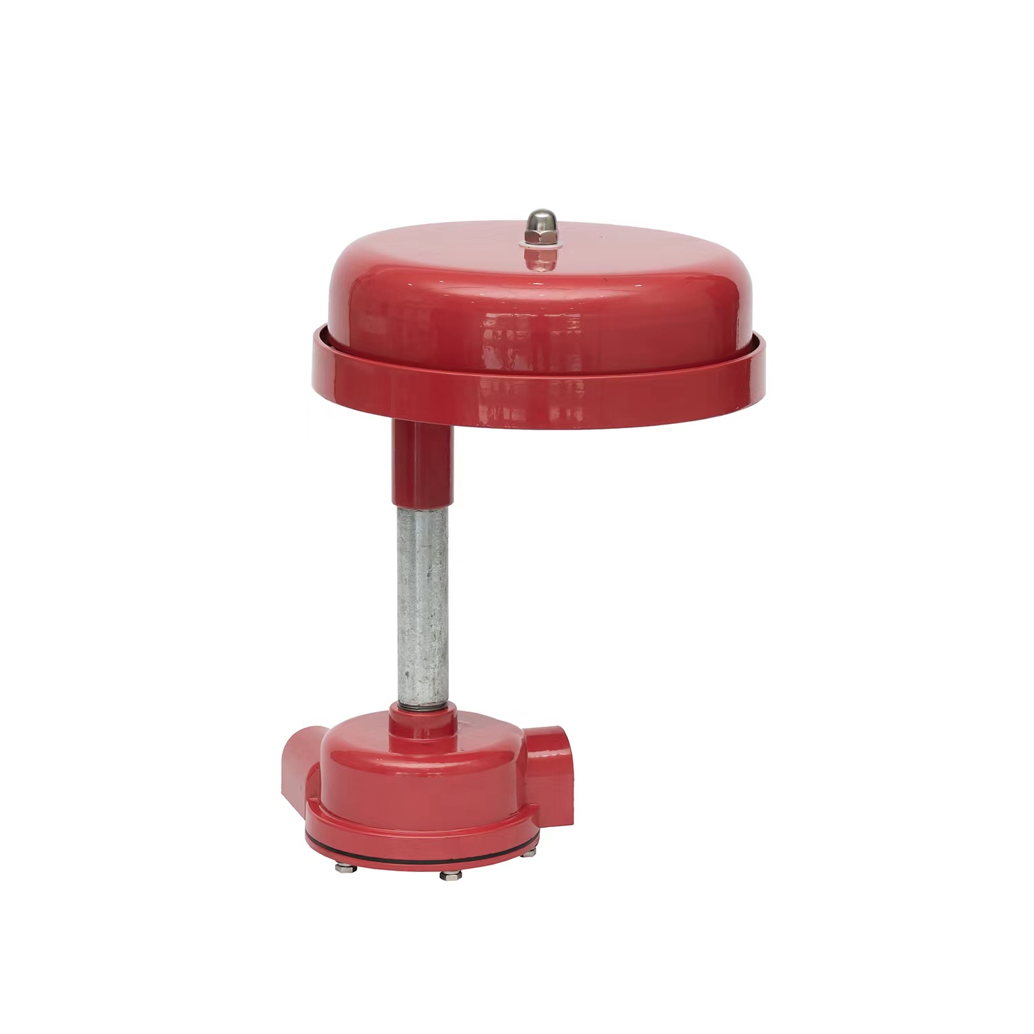
Comparison Chart: Trigger Conditions and Responses
Feature | Water Flow Alarm | Tamper Switch |
|---|---|---|
Primary Role | Detects active water movement | Monitors valve physical position |
Trigger Condition | Flow rate of 10 GPM or more | Valve rotation (2 revolutions or 20% travel) |
Time Delay | Required (Typically 30-45 seconds) | Immediate (Zero delay required) |
Panel Signal Type | Full Emergency "Fire Alarm" | Local "Supervisory" / Trouble Signal |
Building Response | Evacuation strobes / Fire Department dispatch | Local buzzer / Maintenance notification only |
Mounting Location | Directly on main system piping | Directly on water control valves |
Analyzing a water flow alarm vs tamper switch requires understanding their vastly different operating sensitivities. Flow alarms need a minimum flow rate to activate. This rate typically sits around 10 Gallons Per Minute (GPM), simulating the flow of a single activated sprinkler head. However, municipal city water pressure fluctuates constantly. You must account for these normal pressure surges to prevent chaos. Installers utilize mechanical pneumatic dashpots or electronic retard delays for this exact purpose. We usually set these delays between 30 and 45 seconds. This necessary pause prevents irritating false alarms caused by temporary pressure spikes.
Tamper switches operate under an entirely different logic. They act instantly. They must trigger upon any unauthorized valve movement. Fire safety codes strictly require activation within the first two complete revolutions of a valve handwheel. Alternatively, they must trigger within 20% of the total valve travel distance. Partial closure heavily restricts water volume, making immediate notification critical. Tamper switches require absolutely zero delay mechanisms.
The signals these devices send dictate entirely different emergency responses. Flow alarms dispatch the local fire department immediately upon activation. They trigger the building-wide evacuation sequence. Horns sound, strobes flash, and elevators recall to the ground floor. The system assumes a fire is actively burning.
Tamper switches respond much more quietly. They trigger a localized supervisory buzzer at the main Fire Alarm Control Panel (FACP). They simultaneously notify your off-site monitoring company about a specific "trouble" or supervisory state. A closed valve does not mean a fire is happening. Therefore, a tamper switch does not evacuate the building or automatically roll fire trucks. It simply demands urgent maintenance attention.
Physical placement separates these devices clearly. Technicians mount flow alarms directly onto the system piping infrastructure. Depending on the specific model limitations, they can sit on horizontal or vertical pipe runs. Conversely, technicians mount tamper switches directly onto the control valves themselves. You will find them attached to Outside Stem and Yoke (OS&Y) valves, exterior Post Indicator Valves (PIV), or modern Butterfly valves.
Proper electrical integration separates functional systems from constant headaches. You must use separate dedicated circuits on the FACP. This strict separation allows the control panel to clearly distinguish between a critical flow event and a routine tamper event. Mixing these distinct signals on a single zone creates dangerous operational confusion for first responders.
Many commercial facilities rely on dual-switch models for added redundancy. These Single Pole Double Throw (SPDT) configurations offer distinct advantages. One internal switch wires directly to the main control panel. The second internal switch routes independently to a local exterior water motor gong or electric bell. This dual-path approach ensures local occupants hear an alarm even if the primary electronic panel experiences a total failure.
False alarms destroy occupant confidence. Improper flow switch delay calibration creates massive disruptions. Buildings experience fluctuating city water pressure daily. A poorly calibrated retard mechanism will constantly trigger false evacuations whenever the city pumps turn on. Technicians must carefully adjust the pneumatic dashpot to ride out normal surges without delaying real emergency reporting.
Tamper switches face physical, rather than pneumatic, risks. High-traffic utility rooms present constant physical damage hazards. Maintenance workers frequently bump into exposed pipes.
Snapped Actuator Rods: Workers carrying ladders often break the fragile metal rods connecting the switch to the valve stem.
Loose Mounting Brackets: Constant pipe vibration gradually loosens the J-hooks holding the tamper switch housing, causing misalignment.
Water Intrusion: Poorly sealed conduit connections allow condensation to short out the internal microswitches.
Water inherently destroys metal over time. Hard water deposits calcify internal piping networks, but biological threats prove far more aggressive. Microbiologically Influenced Corrosion (MIC) aggressively attacks flow switch components. Specific bacteria living in the stagnant pipe water create highly acidic byproducts. This acid eats away at the metal mounting saddles and plastic flow paddles. Routine internal inspections catch this invisible degradation before the paddle snaps off entirely.
Outdoor environmental factors demand specific hardware protections. Tamper switches mounted on exterior Post Indicator Valves endure extreme weather. You must specify weatherproof NEMA 4 rated housings for these applications. Standard indoor-rated plastic covers will crack under winter ice or degrade under intense summer UV exposure, leading to rapid electrical failure.
The National Fire Protection Association (NFPA) standard 25 outlines strict operational inspection cycles. Facility managers must follow these schedules rigorously to maintain legal occupancy status. You cannot guess when maintenance is due.
Tamper Switch Visual Inspections: You must perform these checks monthly. Technicians look for obvious physical damage, missing covers, or cut wires.
Tamper Switch Physical Testing: You must test the mechanical action semi-annually or annually. The exact frequency depends heavily on your local Authority Having Jurisdiction (AHJ). You physically turn the valve wheel to ensure the panel registers the supervisory signal.
Flow Alarm Physical Testing: You must test these critical triggers quarterly or semi-annually. Testers open the dedicated Inspector's Test Connection valve. This specific pipe simulates the water flow of exactly one open sprinkler head. This process verifies both the paddle movement and the accurate timing of the alarm delay timer.
Ignoring automated safety devices carries immense financial and legal liability. Failing to log and investigate supervisory signals violates most commercial insurance policies. If a panel beeps for weeks regarding a tamper fault, and a fire subsequently destroys the building, investigators will find the ignored signal. Insurance claims face immediate denial under these circumstances.
A broken or bypassed tamper switch creates a severe vulnerability. It essentially compromises the entire sprinkler network by masking a closed water supply. The system appears normal on the control panel, but no water will flow during a crisis. Fire will spread unchecked through the facility simply because a $100 switch failed to report a closed valve.
You cannot simply buy a generic replacement part online. Successful procurement requires evaluating your exact physical infrastructure first. Identify your specific pipe material and thickness schedule. Schedule 10 (thin wall) and Schedule 40 (thick wall) pipes require completely different hardware configurations. The saddle U-bolt sizes and internal paddle lengths vary significantly. If a paddle is too long, it jams against the internal pipe wall. If it is too short, it will not catch the moving water.
Next, carefully identify your specific valve type. An Outside Stem and Yoke (OS&Y) valve operates differently than a modern Butterfly valve. An OS&Y valve uses a rising threaded stem, requiring a specific switch lever mechanism. A Butterfly valve uses an internal rotating disc, requiring a completely different mounting bracket and internal cam switch.
Do not compromise on safety certifications. Your replacement parts must meet rigorous independent testing standards. They must be UL Listed (Underwriters Laboratories). Furthermore, they must carry FM Approval (Factory Mutual) for commercial fire protection use. Installing uncertified components immediately voids your system compliance.
Always check electrical compatibility. Verify your existing FACP brand and its specific voltage requirements. Most modern addressable panels use 24V DC logic, but older legacy systems might run on 120V AC. The new switch contacts must handle the electrical load safely.
Replacing these life-safety components is never a DIY task for general maintenance staff. We strongly recommend bringing in a licensed fire protection contractor to handle the physical swap. Replacing a flow alarm legally requires placing the system on "test" with your alarm monitoring company. You must often drain massive sections of the pipe to remove the old saddle. Legal compliance demands certified expertise at every step of this mechanical process.
Understand the Divide: While both devices remain integral to a functional fire protection network, they serve entirely different masters. One reports an active crisis (water flow), while the other prevents a silent mechanical failure (valve tamper).
Respect the Delay: Flow alarms rely on carefully calibrated retard delays to prevent false alarms from city pressure surges. Never bypass this delay mechanism.
Eliminate the Blind Spots: A broken tamper switch creates a massive blind spot, allowing a maliciously or accidentally closed water valve to go unnoticed until it is too late.
Avoid DIY Replacements: Choosing, installing, and maintaining these components constitutes a strict regulatory requirement demanding certified expertise.
Take Action: Consult with a licensed fire safety specialist for comprehensive system audits or immediate part replacements if your panel currently displays a trouble signal.
A: No, it triggers a supervisory signal or trouble condition at the fire panel, not an evacuation alarm. It notifies building management and the monitoring company that a valve is out of its normal open position. It does not call the fire trucks or sound the building-wide evacuation horns.
A: Yes, NFPA codes strictly require monitoring both the actual water flow and the physical position of the valves controlling that water. They work together. The tamper switch ensures water is available, and the flow alarm confirms water is actually discharging during a fire.
A: False alarms usually occur due to trapped air pockets in the wet pipes, sudden municipal city water pressure surges, or an improperly calibrated retard/delay mechanism. A licensed technician can easily bleed the trapped air and adjust the pneumatic dashpot to ignore normal pressure spikes.
A: The delay is usually set manually between 30 and 45 seconds. This specific timeframe provides enough padding to account for normal municipal pressure fluctuations and minor surges, without dangerously delaying real emergency response times during an actual fire event.