- All
- Product Name
- Product Keyword
- Product Model
- Product Summary
- Product Description
- Multi Field Search

Views: 0 Author: Site Editor Publish Time: 2026-09-23 Origin: Site


Industrial piping systems rely heavily on precise vibration management to maintain safe and continuous operations. A single component failure in this intricate network can bring an entire production facility to a sudden, catastrophic halt. Unfortunately, improper installation of flexible connections directly causes premature equipment failure, pump casing fractures, and severe pipe blowouts. These common field errors completely negate your initial investment in vibration isolation. They also introduce unnecessary safety risks to your maintenance personnel.
Correct positioning ensures maximum vibration dampening and safely accommodates thermal expansion. It actively protects both the sensitive pump nozzles and the adjacent piping infrastructure. Proper setup extends the lifespan of your heavy machinery significantly.
This definitive, engineering-focused guide outlines the exact placement rules for pump-adjacent vibration components. We will examine required supporting hardware, specific configuration types, and critical procurement considerations. Using this framework, you can safeguard your infrastructure, ensure standard compliance, and maintain reliable fluid handling systems.
Engineers often debate the exact distance a vibration isolator should sit from a pump. However, industry guidelines provide clear parameters to optimize system performance. Standard practice aligns closely with Fluid Sealing Association (FSA) recommendations. These guidelines dictate placing the joint one to three pipe diameters away from the pump’s suction and discharge flanges. This specific distance allows the fluid flow to stabilize before entering or after exiting the pump casing.
Placing the joint too far away diminishes its ability to isolate high-frequency mechanical noise. Conversely, bolting it directly to the pump face without rigid anchors can transfer dangerous stress directly onto the pump nozzle. Maintaining the one-to-three diameter rule strikes the perfect balance.
Pumps behave differently on their suction and discharge sides. You must adjust your installation strategy accordingly to match these hydraulic realities.
System maintenance requires strategic component layout. You should generally install the flexible connection strictly between the pump and the shut-off valve. This specific arrangement delivers a massive operational advantage. It allows facility teams to isolate the pump for routine maintenance or repairs. You can service the equipment without draining the entire fluid system. It also prevents you from having to remove the joint itself, saving hours of labor.
Always verify the actual pipe diameter before finalizing your layout. If you use a six-inch pipe, your optimal placement window sits roughly six to eighteen inches from the flange face. Ensure your piping designers mark these exact dimensions on their isometric drawings.
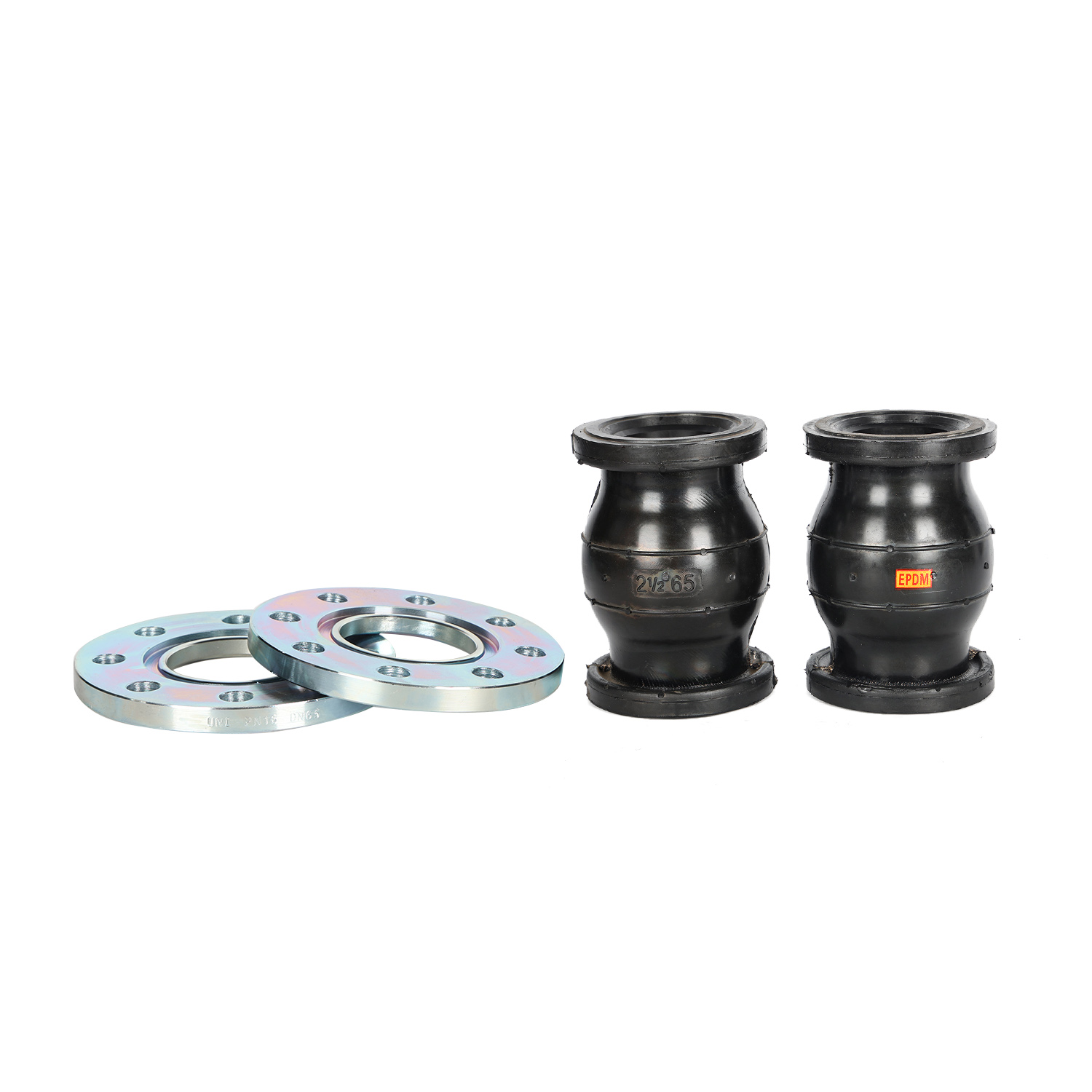
No single vibration isolator works for every industrial application. You must match the specific configuration to your system pressure, structural movement requirements, and pipe dimensions. Selecting the wrong profile often leads to premature rupture or inadequate noise dampening.
Commercial plumbing and standard industrial networks frequently utilize the single ball rubber flexible joint. This design excels in systems experiencing moderate vibration and typical thermal expansion.
Its primary decision factor is space efficiency. It offers a very compact face-to-face dimension. This compactness makes it ideal for tight mechanical rooms or crowded utility corridors. Engineers often specify this type for standard chilled water pumps and cooling tower systems. It delivers reliable performance without demanding excessive installation clearance.
Heavy-duty applications demand more robust solutions. Systems experiencing severe vibration or significant structural settling require a double sphere rubber flexible joint. The dual-arch design grants higher axial compression capabilities and superior lateral deflection.
The core advantage here is unmatched noise reduction. The extra sphere disrupts acoustic waves traveling through the fluid line far better than a single arch. However, this variant requires more installation space. It also strictly mandates the use of control units, as the dual arches become highly susceptible to over-extension under high-pressure surges.
Not all pumping applications involve massive flanged connections. Small-bore piping networks typically require a threaded rubber flexible joint. You will commonly find these components in lines under two inches in diameter.
They serve as the best choice for residential booster pumps, light-commercial water systems, and smaller HVAC applications. The primary decision factor is ease of installation. Plumbers can install them quickly using standard threaded unions. They provide a highly cost-effective vibration solution. However, you must limit their use to lower pressure ratings compared to their heavy-duty flanged counterparts.
Proper component selection means nothing without rigid structural support. A rubber flexible joint acts exactly like a piston under internal system pressure. Fluid pushes against the internal arches, generating a massive thrust force. Without proper anchors, system pressure will stretch the elastomer until it violently ruptures.
You must divide your support strategy into two distinct anchoring methods. Equipment like the pump itself must act as a firm, main anchor attached permanently to the concrete foundation. You cannot rely on piping to hold the pump steady.
Furthermore, you must install directional pipe anchors immediately after the flexible connection. These anchors direct inevitable thermal expansion away from the fragile pump nozzle. They force the pipe to grow along its designated path, rather than buckling backward into the pump casing.
Facility layouts sometimes prevent the installation of absolute main anchors near the pump. When this happens, control rods become non-negotiable safety devices. They act as mechanical limits to prevent catastrophic over-extension.
Control rods limit the axial extension of the unit without restricting its ability to absorb lateral vibration. They utilize heavy steel plates attached to the mating flanges, connected by thick threaded steel rods.
Field technicians often make critical errors during the physical installation phase. You must recognize these red flags to protect your system integrity. Proper oversight prevents localized stress concentrations from destroying the elastomer body prematurely.
We see this dangerous practice constantly in industrial construction. Installers use the flexibility of the elastomer to compensate for sloppy pipe fabrication. A vibration isolator should never bridge a severely misaligned gap.
Forcing the component into a crooked space introduces permanent, severe stress. The elastomer sits in a constantly stretched or twisted state before the pump even turns on. This fallacy drastically reduces the lifecycle of the component. You must ensure mating pipes align perfectly on their true center-lines before bolting anything together.
Rubber bodies handle compression and elongation beautifully, but they fail rapidly under torsional twist. Twisting shreds the internal fabric reinforcement layers. Positioning and tightening must ensure zero rotational force acts on the main body.
You must tighten the flanges systematically. Installers must use calibrated torque wrenches. They must tighten the bolts in a strict, alternating star pattern. Tightening one side completely before moving to the other will crush the bead wire and warp the rubber face. This creates an immediate leak path.
Elastomer joints are exclusively designed to absorb dynamic movement. They must never bear the static dead weight of the adjoining pipe or heavy inline valves. Allowing pipes to sag onto the joint causes the lower half to bulge and the upper half to stretch dangerously.
You must position pipe hangers and robust supports appropriately. These supports isolate the joint from external mechanical loads. The pipe should float freely inside its guides, allowing the vibration isolator to focus solely on dampening pump frequencies.
Procuring reliable components requires strict evaluation frameworks. You cannot base your purchasing decisions on dimensions alone. The chemical makeup of the fluid and industry manufacturing standards dictate product longevity.
You must ensure the specific elastomer material matches the media, temperature, and chemical exposure of your pumping system. An incompatible rubber compound will swell, harden, or dissolve entirely within weeks of operation.
For example, using standard EPDM in a system pumping hydrocarbon-based oils will cause rapid structural degradation. You must consult compatibility charts to verify the correct polymer structure for your exact application.
| Elastomer Type | Common Fluid Media | Maximum Temperature Limit | Best Industrial Application |
|---|---|---|---|
| EPDM | Water, mild chemicals, steam | Up to 250°F (121°C) | Commercial HVAC, cooling towers |
| Nitrile / Buna-N | Oils, petroleum, hydrocarbons | Up to 212°F (100°C) | Petroleum processing, refineries |
| Neoprene | Abrasive slurries, mild acids | Up to 225°F (107°C) | Wastewater treatment, general industry |
Evaluate potential vendors based on their strict adherence to recognized engineering standards. Reputable manufacturers design their components according to FSA (Fluid Sealing Association) guidelines. They also test their raw materials against ASTM D2000 specifications.
Vendors meeting these criteria guarantee consistent wall thickness, verified burst pressure ratings, and reliable flange retention. Avoid unbranded components lacking clear compliance documentation, as they pose a massive blowout risk during pressure surges.
Trustworthy manufacturers stand behind their products, but they require strict accountability from your installation team. Most top-tier vendors require documented proof of proper positioning and control rod installation as a mandatory condition of their warranty.
Prioritize vendors supplying comprehensive torque specifications, material test reports, and detailed installation drawings. A strong technical support team should gladly review your isometric piping plans before you finalize a purchase order.
Successful piping system design relies heavily on protecting your heavy rotating equipment from mechanical stress. Proper positioning near a pump remains a precise calculation involving optimal distance, robust structural anchoring, and highly specific component selection. Ignoring these engineering fundamentals leads directly to costly downtime and hazardous fluid leaks.
To implement these best practices effectively, we recommend taking immediate action. Encourage your mechanical engineers and technical buyers to review current piping isometric drawings against manufacturer submittals. Evaluate your existing unanchored systems for missing control rods. Contact technical sales representatives to request a comprehensive layout review, ensuring your critical infrastructure remains safe, compliant, and highly operational.
A: Yes, and it frequently is, but ensuring the pump is rigidly anchored is critical if placed directly on the nozzle to prevent excessive stress. A direct connection works best when downstream piping has immediate, robust anchoring to handle all thermal expansion forces.
A: Generally, symmetrical rubber expansion joints are bi-directional, but systems with internal flow liners/sleeves must be installed matching the directional flow arrow. Installing a lined unit backward creates severe turbulence, damages the liner, and risks catastrophic flow blockage.
A: If the piping system lacks fixed anchors immediately adjacent to the joint, or if system pressure surges exceed the joint's unanchored pressure rating, control rods must be installed. They act as essential safety limits, preventing the pressure thrust from tearing the elastomer body apart.